|
Notes:
1. Intronix logic analyzer
channels correlate as follows:
| |
Agilent Odd probe D[15..0] =
Intronix D[15..0]
Agilent Even probe D[15..0] = Intronix
D[31..16]
Agilent Odd probe CLK = Intronix CLK1
Agilent Even
probe CLK = Intronix CLK2
(Replace Odd or Even with actual probe
number used, e.g. probe 1 is Odd) |
|
Tektronix probe x0:[7..0] =
Intronix D[7..0]
Tektronix probe x1:[7..0] = Intronix
D[15..8]
Tektronix probe x2:[7..0] = Intronix
D[23..16]
Tektronix probe x3:[7..0] = Intronix
D[31..24]
Tektronix CLK:0 = Intronix CLK2
Tektronix CLK:1 =
Intronix CLK1
(Replace x with actual probe used, e.g. A0:[7..0]
is part of probe A) |
2. Agilent documentation uses the
AMP Mictor pin numbering convention, while Tektronix uses a different
convention. The Mictor pin numbers shown here use the AMP convention.
Tektronix assignments shown here have been converted to the AMP
convention, so they will not "appear" to match Tektronix documentation
(though the physical connections are correct). The MA134 is compatible
with target systems using either convention.
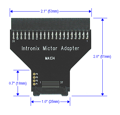
3. Pins 1-4 are
special function pins for Agilent emulators only. Tektronix recommends
connecting these pins to ground. Agilent says not to connect these pins at
all. We recommend leaving them open because Agilent connects power and
signals to these pins. The MA134 brings these pins out to solder pads P1
through P4 which can be used as you see fit.
4. Pins 39-43 are the
large ground pins in the center of the Mictor. Be sure to connect all of
these pins directly to the ground plane in the target system for best
performance.
5. Pin numbers for the 40 pin input header used
by Intronix logic analyzers (shown for reference only).
| Specifications subject to
change without
notice | |

