Active Differential Probe
| Products |
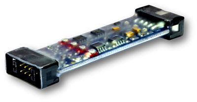
Dual Channel Active Differential ProbeDesigned for BitScope 10, this high performance probe offers some major benefits working with analog signals. It makes possible unreferenced voltage measurement with very good common mode noise rejection allowing simple twisted pair connection to the circuit under test. It has fully compensated high impedance JFET inputs so it can be connected between high impedance nodes in a circuit without adversely affecting circuit operation. It has a switchable x10 prescaler so it can measure very low level signals (i.e. <1mV) over a very wide common mode range (Ā}13.8V). For example, it's ideal for seeing the ripple on a power rail in fine detail or the voltage across a low value shunt resistor to make accurate current measurement. It even offers AC coupling for single ended AC measurements and has a high channel bandwidth (up to 10MHz). BitScope powered, twisted pair connection.You won't need bulky oscilloscope probes nor an external power supply because the performance of simple twisted pairs rivals that of single-ended coaxially connected scope probes and BitScope provides the necessary power.  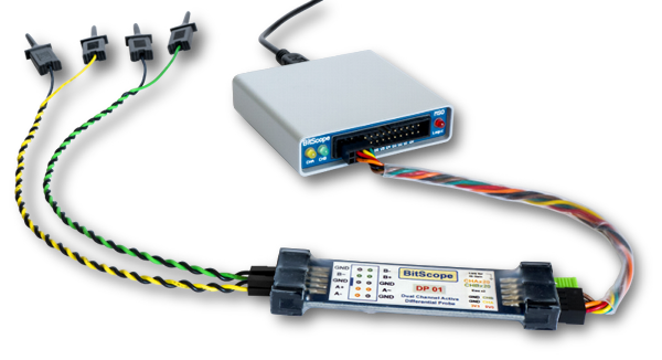 Over comparable connection lengths differential inputs reject noise without the need for complicated coaxial designs (which typically require the use high resistance nichrome conductors to mitigate the capacitance effects of the coaxial cable). In difficult environments or when connecting to more distantly located circuits, low cost shielded twisted pair cabling specifically designed for these purposes (e.g. CAT-5 cables) can be used. Flexible configuration; differential, single ended or AC coupled.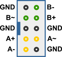
Front Connector Layout DP01 is designed primarily for differential measurements but this does not preclude its use for single ended measurement too. It's also sometimes desirable to make AC coupled measurements so it has provision for this as well. It all comes down to the design of the front IDC-10 connector layout. Each channel is arranged to map across a block of four pins where CH-A and CH-B use idential (rotated) layouts. For differential measurements one simply connect a twisted pair to A+ and A- (or B+ and B-). For a single-ended measurement a 2-pin shorting header (supplied) is connected between A- and the adjacent GND and the twisted pair connected to A+ and the other GND. The same connections may be used for CH-B or one channel may be used in differential mode and the other single-ended. For AC coupled single-ended use the twisted pair is instead connected between A~ and the adjacent GND. 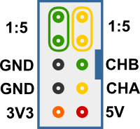
Rear Connector Layout Selectable attenuation and bandwidth.The rear connector is laid out for BitScope Smart Port Interface. It uses a simple 6 conductor cable (as shown below) which connects CH-A, CH-B, 3V3 and 5V power and GND signals required for probe operation. The other two pairs of pins select the attenuation range and bandwidth. When left open-circuit each channel operates in its 2:1 attenuation range. This range has a bandwidth of 10MHz and offers a measureable voltage range of 12Vp-p (over a Ā}13.8V common mode voltage range). 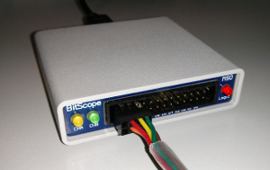
BitScope 10 Connection
If a 2-pin shorting header (supplied) is connected between the CH-A or CH-B pairs (as indicated) the channel operates in its 1:5 gain range. This range has a bandwidth of 3MHz and measurable voltage range of 1.2Vp-p (but still operating over the full Ā}13.8V common mode range). Used in combination with BitScope 10's own gain ranges and 12 bit macro mode it allows differential voltage measurement down to below 1mV anywhere over the -13.8V to +13.8V common range. This makes it ideal for looking at noise (such as ripple) in the presence of high DC bias voltages (e.g. on a 5V or 12V power supply rail). It's also perfect for making voltage measurements across a shunt resistor to calculation circuit current regardless of the bias or common mode voltages appearing at both ends of the resistor. These are things you simply cannot do effectively using a regular scope with single ended inputs.
Probe Voltage RangesThis table enumerates full scale voltage ranges available with DP01 used with BitScope 10. It defines the maximum peak-to-peak signal that can be captured at full resolution with (8 bits in normal mode, up to 12 bits in macro mode). The most sensitive range is 104mV (when the probe is used with the prescaler enabled). 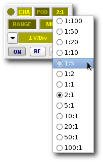 This has a bandwidth of up to 3MHz (if BS10's RF mode is selected) and maximum analog resolution of 500uV. The prescaled ranges reach 1.2V beyond which one can switch to normal range for 10MHz bandwidth and up to 12V measurements. Regardless of the range and prescale setting, the common mode range is always Ā}13.8V. By way of comparison, BitScope 10 itself is shown in the third column in which case the measurements are all single ended and the bandwidth is higher (in RF mode). It's important to note that when the DP01 is used and when its prescaler is enabled, that the appropriate probe scaling is selected in software to ensure correct measurements. With BitScope DSO this is simply a matter of right-clicking the probe scale widget and choosing the right scale. In the example shown here, a probe scaling of 2:1 has already been chosen but the prescaler (1:5) is about to be selected instead. For more information about BitScope DSO please see the online guide. The same scaling selection must be made any other software used with BitScope. Active Differential Probe Specification
Related Posts |
Copyright © 2015 BitScope Designs


